

A week ago we brought our project that we have been working on for the past two months to campus and competed against other 35 teams. After uncountable of all-nighters we have finally achieved our ultimate goal, first place of best designs. Our names are Howard Fan and Samuel Wu and we are two Electrical and Computer Engineering students at the University of Texas at Austin. We have completed the Embedded Systems Design Lab course (EE445L) and would like to share the idea and accomplishments of our winning project. The goal of EE445L course is to design microcontroller-based embedded systems; interfacing from both a hardware and software perspective; and applications, including audio, data acquisition, and communication systems. Throughout the semester the course introduced us to a new aspect of embedded systems design such as interfacing organic light-emitting diode (OLED), analog-to-digital converter (ADC), digital-to-analog converter (DAC), data acquisition system (DAS), wireless communication; designing printed circuit board (PCB); and debugging techniques.
The final lab required us to brainstorm an idea about any embedded system then design and produce the idea. After selecting through several ideas, we decided to build a robotic hand wirelessly controlled by homemade flex sensors glove to enter the final project competition for the course.
DETAILED LISTS
The requirements to enter the competition was to use a custom PCB with Texas Instruments LM3S811 microprocessor and the cost of the entire project needed to be under $30 excluding components obtained from our professors.Tx System (Glove)
- Core of the Tx System
- (1) Texas Instruments LM3S1968 Microcontroller
- (1) 3.3V Voltage Regulator
- (2) Tantalum Capacitors
- Sensors
- (5) 10K Resistors
- (5) Flex Sensors
- Wireless Communication
- (1) XBee 1mW ZigBee Module
- (1) XBee Module Breakout Board
- Power Supply
- (1) Lithium 9V Battery
Rx System (Hand)
- Core of the Rx System
- (1) Texas Instruments LM3S811 Microprocessor
- (1) 3.3V Voltage Regulator
- (2) Tantalum Capacitors
- (1) 6MHz Crystal
- (1) Push Button Switch (Reset Button)
- (2) LEDs
- (1) JTAG Header
- Various of Resistors and Ceramic Capacitors (Please refer to the schematic)
- Motors
- (5) Texas Instruments L293 Quadruple Half-H Drivers
- (5) STP-25N148LVE Unipolar Stepper Motors
- (20) 1N914 Fast Switching Diodes
- (15) 0.1uF Ceramic Capacitors
- Wireless Communication
- (1) XBee 1mW ZigBee Module
- (1) XBee Module Breakout Board
- Power Supply
- (1) 5V DC Wallwart (for the motors)
- (1) 3.3V or above DC Wallwart (for the processor)
HARDWARE
PCB

We decided to use stepper motors because we were able to get them with no cost from the Engineering Science Building check-out desk. The L293 Drivers were used to drive the stepper motors and the 1N914 Snubber Diodes were used to prevent back EMF from the coils.
The power sources of the processor and the motors were separated to prevent accidental power shut down of the processor due to the high current drawn from the motors.

UART0 Tx and UART0 Rx were connected to Din and Dout of the XBee respectively. This schematic also shows the second set of the stepper motors.
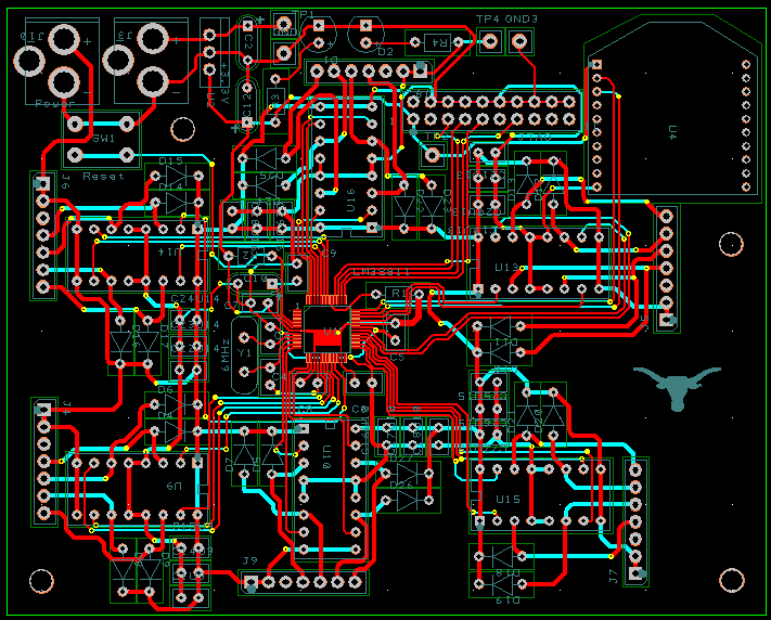
The PCB was completely hand-placed and hand-drawn since we were not allowed to use auto placement and auto route. We made sure there was no traces underneath the 6MHz crystal oscillator and all the bypass capacitors were placed as near to the L293 as possible. We also kept in mind not to have 90 degrees angles when drawing the traces.
SENSORS

We decided to build our own flex sensors because each 4.5" flex sensors would cost us $12.95 + tax which will exceed the $30 budget constraint. Once we confirmed the PCB was working, we began to build our own flex sensors.

We used Velostat pressure sensitive conductive tape because it has the ability to change its resistance when pressure is being applied. We used duct tape on the outside and used two 18 gauge wires which are looped and taped onto two pieces of Velostat tape. Four pieces of zip ties were used on the front and back to provide extra reinforcement.

Another layer of Velostat tape is sandwiched between two wires to create the barrier and now it behaves like a variable resistor.

We connected our sensors in a voltage divider fashion. The top 10k resistors will limit the highest voltage of each ADC while the bottom variable resistors (sensors) changes the ADC values depending on how much they are bent.

An external battery was implemented to keep the glove wireless. Since the glove can wirelessly control the robotic hand, it would be unreasonable for the user to have to plug the glove into the wall. We measured the system using a benchtop power supply and our Tx system consumed about 200mA when it is sampling ADC values. We chose a Lithium 9V battery because it had about 750mAh which can power our system for almost 4 hours. Also, the battery was light in weight and small in size, so it was the best fit for our design. Instead of using a breadboard to stabilize our circuit, we went to RadioShack and bought a PCB prototype board and soldered XBee, 10K resistors, tantalum capacitors, flex sensors, and a 3.3V voltage regulator onto it.
HAND

We had to use something lightweight to build the hand since stepper motors were not very strong. We used 3/4" diameter plastic wiring tube conduit and cut it into different pieces for each individual joints. Separating each joint and use duct tape to connect them can decrease the load for each motor.

We tied one end of the fishing wire to the tip of each finger and the other end to elastic shoe laces. The flat surface of the shoe laces provided a nice track for the stepper motors when they pulled and released and elastic shoe laces also prevented the fishing wires from getting tangled.
SOFTWARE
We developed our project using C on Keil uVision. The system consisted the following modules:
- Tx system on the glove
- ADC.c sampling flex sensors at 125kHz.
- OLED.c displaying the ADC values.
- Calibration.c calibrating each sensor for different size of hands.
- XBee.c transmitting data.
- Rx system on the hand
- XBee.c receiving data.
- Motor.c controlling each stepper motor according to the ADC values.
- Calibration.c calibrating each sensor for different size of hands.
When the system is powered up, the glove will ask the user to hold their hand into a fist for 100 samples and then relax for another 100 samples. Doing this will allow the system to know the maximum and minimum ADC values since different hand size will have different ADC values.
TESTING

Once we received the PCB we began to test our PCB by only soldering the necessary components to run the processor and only one set of motor. We were able to obtain a 5V power adapter from Dr. Valvano so there was no need of an extra voltage regulator.

We began to test the flex sensors on a breadboard before we soldered the components onto the PCB prototype board. We tested the flex sensors by moving each finger individually and observed the ADC values. The consistency of ADC values was also very important because we needed the values to be reproducible.

We spent the past two months to complete the entire project and we were pleased with our design and results. Our project can be said as a combination of all the previous labs throughout the course. In the end, we would like to thank all those who helped us and supported us along the way of development. If you have any question regarding our project please contact us via email at sfan(at)utexas.edu and samuel.wu(at)utexas.edu

HOOK ‘EM!
No comments:
Post a Comment